STEP and IGES: Turning a CAD Solid Into Something You Can Print or Show
A STEP file describes exact mathematical surfaces. A printer and a web viewer both want triangles. This is what happens in between, what you lose, and how to check you lost the right things.
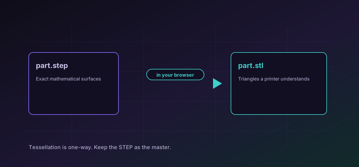
STEP is the file you get when an engineer sends you a part. It is precise in a way that most 3D files are not: it stores the actual mathematics of each surface, so a cylinder is a cylinder rather than a many-sided approximation of one. That precision is exactly why it cannot be handed straight to a 3D printer or dropped into a web page.
Printers and viewers want triangles. Converting a STEP or IGES solid into STL, OBJ or GLB is the step that produces them, and it is a genuine transformation rather than a repackaging. Understanding what changes is the difference between a part that prints correctly and one that arrives faceted, hollow, or the wrong size.
Exact surfaces become an approximation, on purpose#
The technical name for this is tessellation. A curved surface is replaced by a large number of flat triangles that follow it closely. The result is never mathematically identical to the original and is not meant to be. It is meant to be close enough that the difference is smaller than whatever will happen next, whether that is a printer nozzle or a screen. See the STEP format reference for what this site supports.
Pick the target by what receives it#
- STL for 3D printing. Every slicer accepts it, it carries nothing but triangles, and that is precisely why it is reliable. Convert STEP to STL.
- GLB for showing a part on the web or in a viewer. It is self-contained and loads in a browser without a plugin. Convert STEP to GLB.
- OBJ when an older modelling or rendering tool asks for it by name. It is widely understood and comfortably boring.
IGES is the older sibling of STEP and travels the same road. If you have been sent an IGES and the receiving tool is fussy, convert IGES to STL and work from the mesh.
The three things that actually go wrong#
Units#
STL has no unit field. None. A slicer that assumes millimetres will read a part authored in inches as one twenty-fifth of its intended size, and nothing in the file will contradict it. Always check the bounding box in the receiving application before committing material to a print.
Facets you can see#
If a curve looks like a polygon in the output, the tessellation was coarser than the part needed. That is a visible symptom of a real loss of fidelity, and the fix is at the source: export with a finer tolerance, then convert again.
Everything that was not geometry#
Assembly structure, part names, materials, tolerances, threads described as features, and the modelling history all belong to the CAD file. A mesh carries a surface. If a colleague needs any of that, they need the STEP, not the STL.
Check the mesh before you trust it#
- Open the result and look at it. A surprising share of problems are visible in five seconds.
- Compare the bounding box against the dimensions you expect, in the units you expect.
- Check for holes. A mesh with gaps is not watertight and a slicer may refuse it or fill it unpredictably.
- Print or render one test before running a batch through the same settings.
The general habit is covered in verifying conversion results, and the wider 3D picture in converting 3D models between STL, OBJ and GLB.
Troubleshooting
STL carries no units. The source was authored in inches and read as millimetres, or the reverse. Set the unit explicitly in the slicer or re-export from CAD in the unit the receiving tool expects.
The export tolerance was too coarse for the part. Re-export from the CAD application with a finer chord height or angular tolerance, then convert again.
Holes come from surfaces that did not close during tessellation. Re-export from the source solid rather than repairing the mesh, which usually moves the problem rather than fixing it.
A mesh has no assembly tree. Export each component separately from CAD if the parts need to stay distinguishable.
Frequently asked questions
Why can I not print a STEP file directly?
Slicers work on triangle meshes. A STEP file stores exact mathematical surfaces instead, so it has to be tessellated into triangles first. That is what this conversion does.
Can I convert an STL back into a STEP solid?
Not meaningfully. Tessellation discards the underlying mathematics, and nothing in the mesh records that a face was once a cylinder or a fillet. Rebuilding a solid from a mesh is a modelling job, not a conversion.
Which is better for a 3D print, STL or GLB?
STL. Every slicer accepts it and it carries exactly what a printer needs. GLB is the better choice for showing a part on the web, where being self-contained and browser-loadable matters more.
Does the conversion keep my part names and assembly structure?
No. A mesh describes a surface, not an assembly. Names, structure, materials, tolerances and modelling history stay in the CAD file, which is one reason to keep the STEP as the master.
Is my part file uploaded anywhere?
No. The conversion runs entirely in your browser. The geometry is never sent to a server, so there is no stored copy of a file that is often the most commercially sensitive thing in a project.